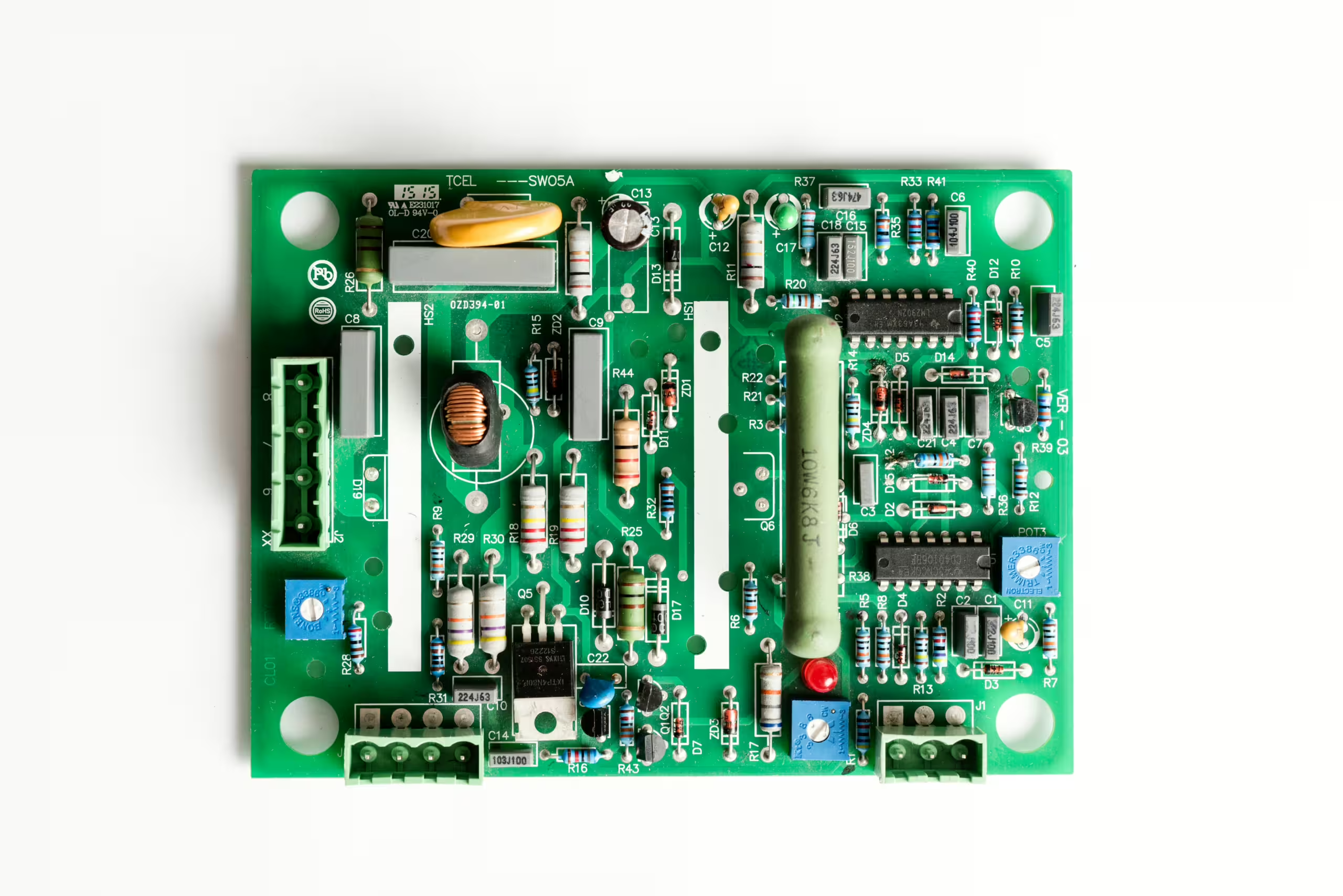
Why are resistors connected in series on signal lines in circuits? It’s common to see resistors with values of 0 ohms, 22 ohms, or higher on the signal lines between two chips. These resistors can sometimes be placed at either the signal transmitting or receiving end. Here are a few reasons for their use:
Impedance Matching and Reducing Signal Reflection At high signal frequencies, when encountering different impedances, signals can reflect similarly to light passing through various materials. If the impedance at the signal source (typically 17-40 ohms) doesn’t match the impedance of the PCB trace (typically 50 ohms), signal reflections can occur at the receiving end. These reflections can cause overshoot, undershoot, or oscillations during signal transitions. By adding a series resistor at the transmitting end, impedance matching can be effectively improved, reducing these reflections.
Absorbing Interference Signals When PCB traces are long or close to fast-switching signal lines, signals are prone to coupling, producing narrow pulses or spikes. This can lead to erroneous operations at the receiving end, increasing the count of false pulses. A resistor connected at the receiving end can absorb these interference signals.
Facilitating Debugging and Testing If the pin layouts of the chips at both ends are dense, measuring signal waveforms or voltages without a series resistor can be challenging. Experienced engineers often include a 0-ohm resistor in the signal line to facilitate debugging and testing. This setup makes it easier to measure and adjust the circuit during development.


