Efficiency is a very common test item in power supply testing, and high efficiency is a goal that many manufacturers continually strive for. In the datasheet of the chip, efficiency curves under several common input and output applications are usually provided. When the actual application range differs from that specified in the datasheet, or when we have made other modifications based on the demo board, we need to retest for efficiency.
Today, I will explain in detail how to conduct efficiency testing and related precautions.
Basic Concepts
Before introducing power supply efficiency testing, let’s first clarify a few definitions and concepts.
Definition of Power Supply Efficiency:
η=Pout/Pin
where the output power Pout=Vo×Io and the input power Pin=Vin×Iin.
It is important to note that Iin is the average input current or the DC current of the power supply. In an ideal state, η=1, meaning a perfect conversion efficiency of 100%, but reality often falls short of this ideal.
So, where does the lost energy go? According to the law of conservation of energy, it is definitely dissipated as heat. For power engineers, improving power supply efficiency and reducing power temperature rise are important tasks. Therefore, we need to accurately test the efficiency of our designed power supply to assess the level of our power supply design.
Relatively speaking, since secondary power supplies are simpler, here we only describe the measurement methods for primary power supplies (secondary power supplies refer to primary power supplies, or the method using four multimeters can also be used).
Below, I will introduce two different methods for measuring the conversion efficiency of a switching power supply. The first method uses a wattmeter and two multimeters; the second method introduces how to measure without a wattmeter, which is not as accurate.
Testing Methods for Primary Power Supplies
The DC output power is simply the product of voltage and current, which can be measured using just two multimeters. We will use a high-precision multimeter to measure the current delivered to the load, and a standard multimeter to measure the output voltage of the power supply.
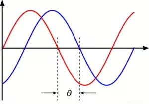
Since there is a phase angle between voltage and current in an AC system, you cannot simply multiply the RMS input voltage by the RMS input current to calculate the input power. Only the active power PP consumed by the power supply must be considered. The reactive power QQ returned to the power supply should not be considered.
Wattmeter (Power Meter)
A wattmeter, also known as a power meter, is an instrument used to measure active power. Electric power includes active power, reactive power, and apparent power, and the same power meter can be used for both AC and DC, primarily used in fields such as power, electrical measurement, and metering.
If classified by the connection method in the test system, power meters can be divided into terminal type and through type.
Choosing the power range of a power meter is actually about correctly selecting the voltage and current range of the power meter. It is crucial to ensure that the maximum working current and highest voltage of the load do not exceed the current and voltage range of the power meter, thereby naturally satisfying the power range of the power meter. Conversely, if only the power range is considered during selection, without taking into account whether the current and voltage range fit the load current and voltage, it might damage the power meter.